VAPOR COMPRESSION DISTILLATION (VCD)
Improperly known as thermo-compression or mechanical vapor re-compression (MVR), a Vapour Compression Distillation system produces water for pharmaceutical use, more precisely for I.V. fluids, injectables, infusion and specialist solutions, washing systems and for all products where sterility, elimination of pyrogens and Chlorine solvents and other external substances with low molecular weight are a critical quality attribute.

Bram-cor’s Vapor Compression Distiller (STMC) has been an integral component of our reliable and cost-effective high purity water systems.
With 19 models of Vapor Compression Distillation units ranging from 17gph to 6,600gph and heating media choices (steam or electric), we have a unit perfectly suited for your application.
The resultant distillate is free from Oxygen, Carbon Dioxide, Chlorine solvents, Salts and Heavy Metals, which are eliminated by two de-gassing systems. For example, considering an infeed water with a conductivity not higher than 1 μS, the STMC distiller can produce a distillate at 25/30°C at a conductivity of 0.08 μS/cm and a pH of 6,9÷7.
The Vapor Compression Distillers always operate at an internal pressure higher than atmospheric, preventing outside air from entering the plant. In every distillation phase, the distillate is always at a pressure higher than the feed water ensuring the feed water will never enter the distillate circuit if there is any leakage.

The STMC Distillers can work with electric heating (STMC EL), 3 bar steam heating (STMC ST), or both (STMC ES). The last type of heating is useful when the distiller works 24 hours/day or if there is a lack of industrial steam overnight.
Special care is given to the choice of sanitary materials. Product-contact surfaces are in certified AISI 316L stainless steel, with standard roughness ≤ O.4µm. PFTE gaskets ensure perfect sealing. Advanced Process Analytical Technologies are applied for monitoring issues and professional GAMP compliant automation is provided for system control.
VCD CONSTRUCTION CRITERIA
COMPRESSOR
Compressors are now available that operate both at high and low speeds, with the lower speeds creating better operating efficiency. Compressors have evolved from high speed centrifugal designs (10,000 rpm) which are belt-driven to lower speed (3,600-5,00 rpm) direct drive systems which use less energy. A further enhancement has been the multistage blower compressor which runs under 4000 rpm, significantly reducing operating noise level (below 65-70 dB) and maintenance. A standardized approach to mechanical seal design can also reduce the maintenance time typically associated with their changeover as well as prevent or minimize leakage over a longer operating period. The issue of non-condensable gas removal is as standard addressed by vapor compression designs by preceding the compressor with a deaerator.
EVAPORATION
As with multiple-effect designs, there are different approaches to evaporation. Evaporators will either be mounted vertically or horizontally. A vertically-mounted compressor will evaporate water on either a falling film or thin rising film principle for drier steam, whereas spray film units direct water over the horizontal surface area of the evaporation tubes for a more wetted surface. Since the separation of impurities from the steam is done by more of mechanical process (vs. multi-effect’s centrifugal action) a secondary separation system is in place. Commonly, a demister pad is used but a newer approach utilizes a baffle similar to those found in multiple-effect stills for a design which is considered more sterile as it is fully drainable. Typically, evaporator tubing is not electropolished as standard due to the lower susceptibility of scale, but is now either a standard or at least a standard option.
BENEFITS OF BRAM-COR STMC
Bram-cor’s STMC Vapor Compression Distillers can produce both cold Distillate or hot Distillate with huge savings of energy costs and with no need of cooling water. STMC distillers operate with electrical heating or plant steam heating or even through both electrical and steam heating systems. The recognized benefits of the Vapor Compression Technology are:
- Low energy consumption, no need of cooling water to condensate the pure steam
- No need for high quality inlet water (in some cases even softened water can feed the VC still)
- Very high quality of the WFI thanks to the strong degassying process
- No need to pressurize the inlet water
- WFI outflow at high pressure (1 – 1.5 bar) without any additional pump
- Extreme safe process, with no risk of any cross contamination through plant steam or inlet water
- Highest flexibility in terms of capacities and WFI temperatures
- Reduced maintenance
A full automation ensures easy operation and total monitoring of critical parameters, by means of certified in-line instruments and of a careful alarm policy. Access policy and records can be managed according to 21 CFR PART 11.
THE MAIN PROCESS STEPS OF
VAPOR COMPRESSION DISTILLATION
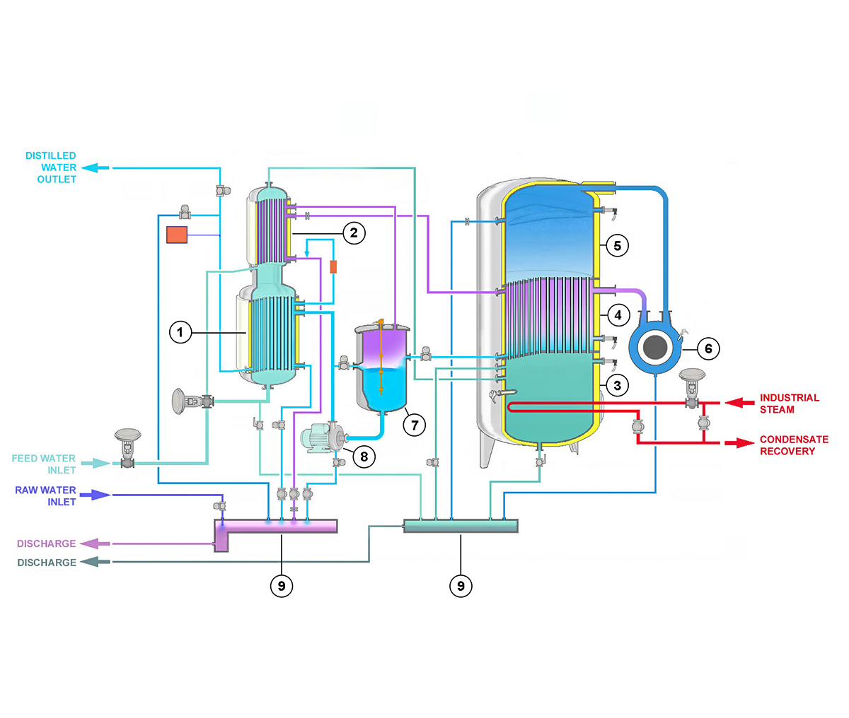
STEP 1 Feed-water enters into the first (optional) heat exchanger (1) (tube side) and is pre-heated, cooling at the same time WFI to the temperature setup in the Operator Panel.
STEP 2 An automatic system (optional) regulates feed-water flow passing through phase 1, thus regulating WFI temperature.
STEP 3 Feed water goes into in the second heat exchanger (2) (tube side), and is furthermore pre-heated, condensing the gas generated by WFI production process.
STEP 4 Heated water flows in tank (3). Water level is controlled by an automatic system, operated by two pressure transducers. The pipes in condenser (4) are partially filled by feed-water.
STEP 5 The heater (either electric and/or steam-heated) increases feed-water temperature to evaporation temperature. The generated pure steam occupies the dome (5). An automatic system regulates the thermal intake of the heating system, in order to keep the pressure in the dome at the setup value.
STEP 6 A blower (6) sucks in the pure steam present in the dome (5) compressing it into the shell side of the condenser.
STEP 7 Pure steam condenses in the shell side of the condenser (generating WFI) yielding energy to the feed-water contained in the condenser pipes, which now evaporates, generating other pure steam.
STEP 8 The produced WFI comes out of the condenser and flows into the recirculating tank (7). The gases released during WFI production process go into the shell side of the heat exchanger (2).
STEP 9 WFI is then collected in the recirculating tank (7) and pressurized by the pump (8), through the heat exchanger (1) (optional), where it reaches the temperature, setup in the Operator Panel.
STEP 10 A measuring system continuously monitors WFI quality (conductivity and temperature), and diverts WFI to the storage tank (conform WFI) or to the distiller drain manifolds (9) (substandard WFI).